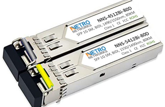
NNS-4512Bi-80D & NNS-5412Bi-80D

NNS-4512Bi-80D & NNS-5412Bi-80D
SFP 1G, SM, BiDi
Short Description
1.25Gbps SFP BIDI 1490/1550nm (1550/1490nm) 80km Transceiver With DDM Function
Application:
- Gigabit Ethernet
- Switch to Switch Interface
- Gigabit Fiber Channel
- Switched Backplane Applications
- Router/Server Interface
Glight SFP transceivers support the 2-wire serial communication protocol as defined in the SFP MSA. The standard SFP serial ID provides access to identification information that describes the transceiver’s capabilities, standard interfaces, manufacturer, and other information.
Additionally, Glight SFP transceivers provide a unique enhanced digital diagnostic monitoring interface, which allows real-time access to device operating parameters such as transceiver temperature, laser bias current, transmitted optical power, received optical power and transceiver supply voltage. It also defines a sophisticated system of alarm and warning flags, which alerts end-users when particular operating parameters are outside of a factory set normal range.
The SFP MSA defines a 256-byte memory map in EEPROM that is accessible over a 2-wire serial interface at the 8 bit address 1010000X (A0h). The digital diagnostic monitoring interface makes use of the 8 bit address 1010001X (A2h).
The operating and diagnostics information is monitored and reported by a Digital Diagnostics Transceiver Controller (DDTC) inside the transceiver, which is accessed through a 2-wire serial interface. When the serial protocol is activated, the serial clock signal (SCL, Mod Def 1) is generated by the host. The positive edge clocks data into the SFP transceiver into those segments of the E2PROM that are not write-protected. The negative edge clocks data from the SFP transceiver. The serial data signal (SDA, Mod Def 2) is bi-directional for serial data transfer. The host uses SDA in conjunction with SCL to mark the start and end of serial protocol activation. The memories are organized as a series of 8-bit data words that can be addressed individually or sequentially.
Recommended Operating Conditions: ParameterSymbolUnitMin.Typ.Max. Storage TemperatureTSTG°C-40 85 Operating Case TemperatureTOP°C0 70 Power Supply VoltageVCCV3.13.33.5 Data Rate Gb/s 1.25 Transmitter Specifications ParameterSymbolUnitsMin.Typ.Max.NotesAverage Output Optical Power P0dBm-2 3 Transmitter Off Optical Power POFFdBm -45 Output Center Wavelengthλnm147014901510DFB-LD 153015501570DFB-LDSide Mode Suppression RatioSMSRdB30 Extinction RatioERdB9 Optical Rise Time-ps 260 Optical Fall Time-ps 260 Jitter P-PTJUI 0.1Note 1Optical Eye DiagramCompliant with IEEE Std 802.3z Note 1: Measured at 1.25Gbps PRBS27-1. Electrical Characteristics ParameterSymbolUnitsMin.Typ.Max.NotesTotal Supply CurrentICCmA–300 TransmitterSingle Ended Data Input SwingVPPmV200-1200 Differential Input ImpedanceZINohm80100120 Tx_Fault Output Voltage- HighVOHV2-Vcc Tx_Fault Output Voltage- LowVOLV0-0.8 Tx_Dis Input Voltage- HighVIHV2-Vcc Tx_Dis Input Voltage- LowVILV0-0.8 ReceiverSingle Ended Data Output SwingVPPmV300-600 LOS Output Voltage- HighVLOSHV2– LOS Output Voltage- LowVLOSLV–0.8 Receiver Specifications ParameterSymbolUnitsMin.Typ.Max.NotesSensitivitySendBm -26Note 1Saturation Input Optical PowerSatdBm-3 LOS Assert LevelLOSAdBm-40 LOS Deassert LevelLOSDdBm -27 LOS HysteresisHYSdB0.5 6
- Up to 1.25Gbps data rate
- Duplex LC receptacle optical interface compliant
- Single +3.3V power supply
- Digital Diagnostic Monitoring function implemented
- External calibration
- Hot-pluggable
- AC coupling of PECL signals
- Receiver Loss of Signal Output
- Transmitter disable input
- Compliant with SFF-8472
- Compliant with IEEE802.3z Gigabit Ethernet
- International Class 1 laser safety certified
- Operating temperature range: 0oC ~+70oC
- RoHS Compliance

